ESP32-CAM WiFi Bluetooth Camera Development Board
Compact IoT Module for Wireless Surveillance and Vision Projects
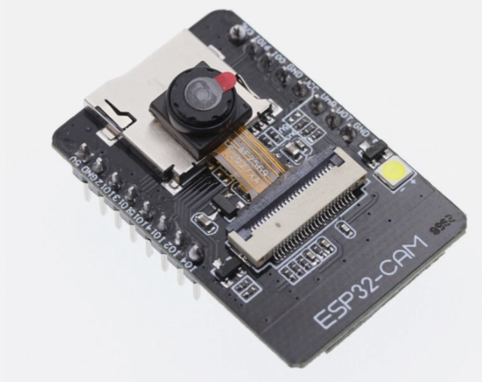
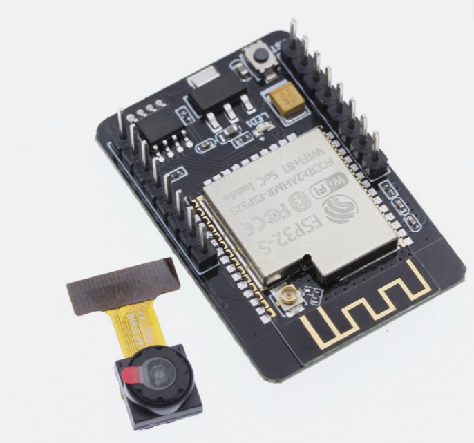
The ESP32CAM is a powerful, lowcost development board that combines a dualcore ESP32 processor with an OV2640 camera sensor, WiFi, and Bluetooth in a tiny form factor (27x40.5x4.5mm) [citation:1][citation:5]. It is an ideal solution for wireless monitoring, smart home devices, industrial control, and AI vision applications like face detection and QR recognition [citation:1][citation:6].
DualCore Processor & Camera Xtensa LX6 CPU up to 240MHz with 2MP OV2640 camera [citation:12]
Builtin WiFi, Bluetooth & Storage - 802.11 b/g/n, BLE 4.2, and MicroSD card support [citation:1][citation:2]
Power requirement is 5V DC at a minimum of 2A; insufficient power causes image distortion [citation:1][citation:4][citation:5]
For programming without an external FTDI adapter, use the ESP32CAMMB base board with USB connectivity [citation:7]
The ESP32CAM has no builtin USB port; use a USBtoSerial programmer (e.g., FTDI) connected to the UART pins or the MB base board for uploading code [citation:12]
Technical Specifications
| Parameter | Value |
|---|
| :- | :- |
| Processor | ESP32S DualCore Xtensa LX6 [citation:5][citation:6] |
| Clock Speed | Up to 240MHz [citation:10][citation:12] |
| Flash Memory | 32Mbit (4MB) default [citation:1][citation:5] |
| PSRAM | 4MB or 8MB external (varies) [citation:1][citation:3] |
| Wi-Fi | 802.11 b/g/n/e/i (2.4GHz) [citation:1][citation:5] |
| Bluetooth | 4.2 BR/EDR and BLE [citation:1][citation:5] |
| Camera Sensor | OV2640 (2MP) [citation:6][citation:8] |
| Image Output | JPEG (OV2640), BMP, GRAYSCALE [citation:1][citation:4] |
| IO Pins | 9 (shared with camera interface) [citation:1][citation:5] |
| MicroSD Card Support | Up to 4GB [citation:1][citation:4] |
| Power Supply | 5V DC (4.75-5.25V) [citation:1][citation:4] |
## Key Features
DualCore Processing 600 DMIPS computing power for complex vision tasks [citation:10][citation:11]
Integrated Wireless WiFi and Bluetooth for remote streaming and control [citation:6][citation:9]
OV2640 Camera - Captures images up to 2MP and supports JPEG output for efficient transmission [citation:3][citation:8]
MicroSD Card Slot - Local storage for captured images and files [citation:1][citation:6]
Multiple Sleep Modes Deep sleep current as low as 6mA for lowpower operation [citation:1][citation:3]
Flash Lamp Builtin LED for low-light conditions [citation:2][citation:5]
= Applications =
- Wireless surveillance and home security cameras [citation:1][citation:6]
- Remote monitoring for smart agriculture and industrial inspection [citation:6][citation:10]
- Face detection and recognition projects [citation:7][citation:12]
- QR code and wireless identification systems [citation:1][citation:4]
- DIY robotics vision modules [citation:6][citation:12]
Affordable Vision Platform One of the most costeffective solutions for IoT and camera projects [citation:6][citation:12]
Versatile Connectivity WiFi, Bluetooth, and GPIOs for flexible project integration [citation:1][citation:5]
√ Works with Arduino IDE, ESP-IDF, and MicroPython [citation:7][citation:8]
√ External antenna support and PCB antenna option available [citation:1][citation:10]
√ Compact size ideal for portable and space-constrained projects [citation:1][citation:5]
Key Pinout Information
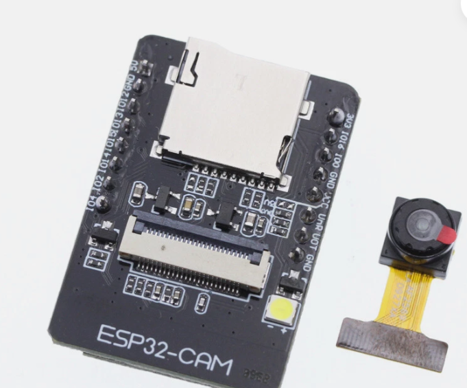
The ESP32-CAM has three power pins (5V, 3.3V) and three GND pins [citation:1][citation:4]. The UART pins (GPIO1 TX, GPIO3 RX) are used for programming, and for uploading code, GPIO0 must be connected to GND to enter flashing mode [citation:1][citation:4].
The MicroSD card slot uses the following pins internally [citation:1][citation:4]:
- GPIO14: CLK, GPIO15: CMD, GPIO2: Data 0, GPIO4: Data 1, GPIO12: Data 2, GPIO13: Data 3.
For programming, use a USBtoSerial adapter or the ESP32CAMMB base board (which includes a USB port for simplified operation) [citation:7].
The GPIO4 pin is also connected to the onboard LED—consider this when using the MicroSD card [citation:1][citation:4] or controlling external devices.
Do not pull GPIO0 high or low during normal operation, as it is connected to the camera XCLK signal and must be left floating [citation:1][citation:4].
The power supply must be capable of delivering at least 2A; otherwise, the camera image may have horizontal colored lines or water ripples [citation:1][citation:4][citation:5].
## Troubleshooting
No image or distorted image:
- Ensure power supply provides 5V 2A minimum (not just 1A) [citation:1][citation:4][citation:5]
- Pull GPIO32 pin LOW during camera operation [citation:1][citation:4][citation:5]
- Check camera module is properly seated in the connector
ESP32-CAM not detected for programming:
- Install CH340/CP2104 USB driver for the programmer [citation:7]
- Use a datacapable USB cable (not chargeonly) [citation:7]
- Connect GPIO0 to GND before powering on to enter flashing mode [citation:1][citation:4]
Wi-Fi connection issues:
- Connect to a 2.4GHz network (not 5GHz) [citation:6][citation:12]
- Verify SSID and password in the code
- Check signal strength and antenna connection