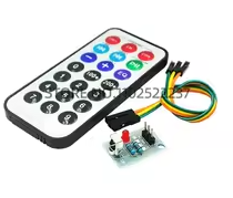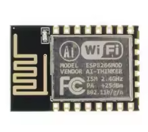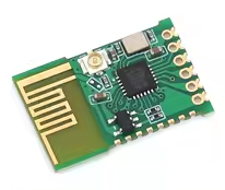
Remote control switch 2.4G module JDY-41 wireless serial transparent transmission module transceiver
KSH 350.00
Out of Stock
The JDY-41 is a 2.4G wireless serial module designed for transparent transmission and remote control switching. It enables wireless UART communication and direct IO switch control without external MCU.
| Parameter | Value |
|---|---|
| Model | JDY-41 |
| Frequency | 2.4GHz ISM band |
| Transmit Power | Up to 12dB |
| Receive Sensitivity | -96dB |
| LineofSight Range | 160 meters |
| UART Baud Rate | 1200 to 38400 bps |
| Tx Current | 40mA |
| Rx Current | 24mA |
| Sleep Current | 10uA |
= Key Features =
Transparent Serial Mode Direct UART passthrough without AT commands
Learning Remote Control - Supports ID learning for selective response
Acknowledgment Mode - Confirms data receipt at destination
Configurable IO Pins - 8 GPIO pins for switch/control applications
Low Power Sleep - 10uA sleep current for battery operation
√ Configurable via AT commands
√ Supports pointtopoint and broadcast modes
√ Compatible with 3.3V logic systems
| Pin | Name | Function |
|---|---|---|
| Pin 1-8 | GPIO1-8 | Configurable input/output pins |
| Pin 9 | VCC | 2.2V to 3.6V power |
| Pin 10 | RXD | Serial receive input |
| Pin 11 | TXD | Serial transmit output |
| Pin 12 | SET | Configuration mode (low to enter) |
| Pin 13 | CS | Chip select / sleep control |
| Pin 14 | GND | Ground |
> Connect VCC to 3.3V supply only
Enter AT command mode:
Transparent mode:
No communication:
Short range: