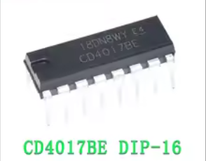
CD4017BE Decade Counter/Divider IC
Versatile CMOS 10-Output Johnson Counter for Digital Projects
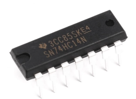
The CD4017BE is a 5-stage Johnson counter that provides 10 decoded outputs for sequential counting applications. This Texas Instruments IC is a classic component in digital electronics, widely used for LED chasers, frequency dividers, and timing circuits.
10 Decoded Outputs - Sequentially activates outputs Q0 through Q9 with each clock pulse
Wide Operating Voltage - Works from 3V to 18V for flexible project integration
Clock frequency is 5.5MHz maximum with Schmitt trigger action for pulse shaping
For cascading multiple ICs, connect the Carry-Out (pin 12) to the next IC's Clock Input (pin 14)
Outputs can directly drive LEDs, but current per pin is limited to about 10mA
Technical Specifications
| Parameter | Value |
|---|
| Logic Type | Decade Counter / Divider |
| Outputs | 10 decoded (Q0-Q9) |
| Clock Frequency | 5.5MHz |
| Supply Voltage | 3V to 18V |
| Package | 16-Pin PDIP (Dual Inline) |
| Operating Temperature | -55°C to +125°C |
| Technology | CMOS 4000 series |
= Key Features =
Schmitt Trigger Clock Input - Allows unlimited clock pulse rise and fall times
Asynchronous Reset - High signal on pin 15 clears counter to zero
Clock Inhibit Function - Pin 13 disables clock when high
CarryOut Output Pin 12 for cascading multiple counters
Fully Static Operation - No minimum clock frequency
Direct LED Drive - Outputs can power LEDs with external resistors
= Applications =
- LED chasers and light sequencers
- Frequency division and clock division
- Decade counter/decimal decode displays
- Sequential switching circuits
- Timer and control logic circuits
- Digital counter and divider projects
Classic and Reliable - Decades of proven performance in hobby and industrial projects
Easy to Use - Simple pinout with clear output sequencing
√ DIP package ideal for breadboard prototyping
√ Works with Arduino, 555 timers, and other logic circuits
√ Multiple outputs cascade for longer counting sequences
Pin Configuration
- *Pins 17, 911*: Q0-Q9 decoded outputs
- *Pin 8*: Ground (Vss)
- *Pin 12*: Carry-Out (ripple clock output)
- *Pin 13*: Clock Inhibit (disables clock when high)
- *Pin 14*: Clock Input (rising edge triggered)
- *Pin 15*: Reset (high resets counter to Q0)
- *Pin 16*: Vdd (3V to 18V power)
Connect unused outputs to ground or leave open
To cascade multiple 4017s, connect each IC's Carry-Out to the next IC's Clock Input
Do not exceed 18V supply or 10mA per output
Pin 13 must be low for counting to occur
Troubleshooting
Counter not advancing:
- Check Clock Input (pin 14) for proper signal
- Ensure Clock Inhibit (pin 13) is low
- Verify Reset (pin 15) is low
Outputs not lighting:
- Check current-limiting resistors on outputs
- Verify Vdd and Vss connections
- Ensure outputs are active (only one high at a time)
Wrong output sequence:
- Check for correct clock signal direction
- Verify Clock Inhibit is not accidentally triggering