L298 Motor Driver Module
KSH 500.00
In Stock
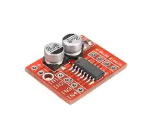
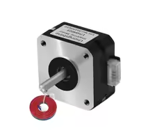
The L298N motor driver module is a highpower controller board that uses the *L298N dual fullbridge driver IC* to control two DC motors or one stepper motor [citation:1][citation:6]. It allows independent speed and direction control for each motor, making it a staple for Arduino robotics projects [citation:2][citation:3].
The module pins are grouped into power, control, enable, and motor outputs [citation:5][citation:8][citation:12].
| Pin Name | Function |
|---|---|
| :- | :- |
| *VCC (12V)* | Motor power input (5V-35V) |
| *GND* | Common ground for power and logic |
| *5V* | Logic supply input OR output (jumper dependent) |
| *IN1, IN2* | Direction control pins for Motor A |
| *IN3, IN4* | Direction control pins for Motor B |
| *ENA* | Enable / PWM speed control for Motor A |
| *ENB* | Enable / PWM speed control for Motor B |
| *OUT1, OUT2* | Terminals for connecting Motor A |
| *OUT3, OUT4* | Terminals for connecting Motor B |
## Key Features and Applications
+High Current Capacity - Handles up to 2A per channel, with 3A peak current [citation:10].
+Onboard 5V Regulator - Can supply power to an Arduino when motor voltage is ≤12V [citation:1].
+Heat Sink for Better Performance Builtin heat sink for improved thermal management [citation:4].
+PWM Speed Control - Use PWM signals for smooth speed variation [citation:2][citation:3][citation:5].
+Simple Logic Interface - TTL compatible 5V logic inputs [citation:4][citation:10].
+Stepper Motor Support - Can drive a bipolar stepper motor [citation:9][citation:10].
## Common Applications
## Wiring and Operation Guidelines
The direction of the motor is controlled by the logic states of the IN pins [citation:1].
| ENA | IN1 | IN2 | Motor A State |
|---|---|---|---|
| :- | :- | :- | :- |
| 0 | X | X | Stop |
| 1 | 0 | 0 | Brake |
| 1 | 0 | 1 | Rotate Forward |
| 1 | 1 | 0 | Rotate Reverse |
| 1 | 1 | 1 | Brake |
For speed control, send a PWM signal (e.g., using analogWrite()) to the ENA/ENB pin. This varies the motor's average voltage, controlling its speed [citation:2].






 2.png "Buy MQ-5 Gas Sensor Module for KSH 600 – HIMASTORES Mombasa – Quality electronics in Mombasa, Kenya")