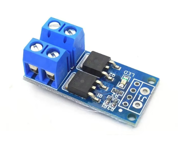
15A 400W MOS FET Trigger Switch Drive Module DC 5V-36V PWM Regulator Control Panel Motor control board – KSH 150 at HIMASTORES Mombasa – best electronics in Kenya

15A 400W MOS FET Trigger Switch Drive Module DC 5V-36V PWM Regulator Control Panel Motor control board

SKU: HMJ819 Category: Motors
KSH 150.00
Out of Stock

Product Description

15A 400W MOS FET Trigger Switch Drive Module

High-Power PWM Regulator Control Panel for Motors

This MOS FET trigger switch drive module handles 15A and 400W loads with DC 5V36V input. Ideal for motor control and highcurrent switching applications using PWM regulation.

High Current Capacity - 15A continuous load handling
Wide Voltage Range - Operates from 5V to 36V DC
Use heatsink for loads above 10A
Apply 5V trigger signal for activation
Do not exceed 36V or 15A ratings

Technical Specifications

ParameterValue
Load Current15A max
Power Rating400W max
Input Voltage5V to 36V DC
Trigger Signal3.3V to 20V
Control TypePWM / Digital
Switching FrequencyUp to 20kHz
MOS FET TypeN-Channel

= Key Features =

High Power Handling - 400W capacity

PWM Compatible - Speed and intensity control

Optocoupler Isolation - Protected input

Fast Switching - 20kHz capability

LED Status Indicator - Visual operation feedback

= Applications =

  1. DC motor speed control
  2. LED dimming systems
  3. Heater power regulation
  4. Pump control
  5. Power tool speed control
  6. Robotics motor drivers
Industrial Grade Reliable highcurrent switching
Simple Control - Trigger with any microcontroller

√ Includes terminal blocks for wiring

√ Opto-isolated input protection

√ Ready for PWM signals

Connection Guide

Terminal connections:

  • VCC: 5V to 36V power input
  • GND: Power ground
  • LOAD+: Positive output to load
  • LOAD-: Negative output to load
  • SIG: Trigger/PWM input
  • SIG-: Signal ground
Connect load between VCC and LOAD- for switching

Use PWM signal for speed dimming control
Ensure adequate wire gauge for 15A
Use flyback diode for inductive loads

Wiring Examples

For motor control:

  • Connect motor positive to VCC
  • Connect motor negative to LOAD-
  • Apply PWM to SIG pin
  • Motor speed varies with PWM duty cycle

Simple Setup - Only three control wires

Versatile Control - Digital or PWM signals

95% efficiency at full load
Proven in thousands of applications

√ Opto-isolated for microcontroller safety

√ Screw terminals for secure connections

√ Works with 5V and 3.3V logic

Protection Features

Built-in safeguards:

  • Optocoupler isolation
  • Reverse polarity protection
  • Overcurrent protection
  • Thermal protection
Add external fuse for additional safety
Mount on metal plate for heat sinking
Do not run at 15A without cooling
Keep away from flammable materials

Troubleshooting

Module not switching:

  • Check trigger signal voltage
  • Verify power connections
  • Avoid low trigger voltage

Overheating:

  • Reduce load current
  • Add heatsink
  • Avoid continuous high load