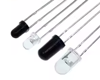
5mm 940nm Infrared Emitter and IR Receiver LED 301A for Arduino
Reliable IR Pair for Remote Control and Sensor Projects
This 301A pair set includes infrared emitting diodes and phototransistor receivers, both matched to the 940nm wavelength for optimal signal transmission. With a 5mm diameter package, they are ideal for DIY remote control, obstacle detection, and automated systems using Arduino or other microcontrollers [citation:1][citation:7].
Matched Pair - Both emitter and receiver tuned for 940nm operation
Reliable Signal Transmission Up to 78 meters range [citation:4][citation:5][citation:10]
Forward voltage: 1.2V to 1.5V (emitter); Receiver output: TTL level [citation:4][citation:9]
Use a current-limiting resistor (100Ω to 220Ω) in series with the emitter [citation:1][citation:9]
The receiver responds only to pulsed/modulated signals (e.g., 38kHz carrier), not a constant DC beam [citation:1]
Technical Specifications
| Parameter | Emitter (LED) | Receiver (Diode) |
|---|
| Wavelength | 940nm | 940nm |
| Forward Voltage | 1.2V - 1.5V | N/A |
| Continuous Current | 20mA - 100mA | N/A |
| Peak Pulse Current | 1000mA | N/A |
| Receiving Angle | N/A | ~40 degrees |
| Material | 5mm diameter | 5mm diameter |
= Key Features =
Matched Spectrum - Emitter and receiver are tuned to 940nm, ensuring maximum signal strength [citation:1]
Common 5mm Package - Standard footprint fits breadboards and PCBs easily [citation:7]
Phototransistor Receiver Outputs a TTLcompatible signal, ideal for connecting directly to a microcontroller pin with a pull-up resistor [citation:1][citation:9]
Small Size - Easy to position for obstacle detection modules
= Applications =
- DIY remote control for TV, fan, or robot
- Linefollowing or obstacleavoidance robot sensor
- Contactless RPM measurement (tachometer)
- Security system beam break detection
- Educational electronics projects
Most Common Standard - 940nm is the widely used wavelength for consumer IR [citation:1][citation:3]
Easy to Use - Compatible with IRremote library for rapid development [citation:1]
√ Through-hole design compatible with Arduino sensor shields
√ Pack of 10 pairs available for multiple projects [citation:3][citation:6][citation:7]
Connection Guide
*Wiring the Emitter (LED):*
- Connect the anode (longer leg) to a digital output pin via a ~220Ω resistor.
- Connect the cathode (shorter leg) to GND.
- Send a modulated signal (e.g., using the IRremote library) for effective communication [citation:1][citation:9].
*Wiring the Receiver (Phototransistor):*
- Connect the collector (often the longer leg) to VCC (3.3V or 5V) through a 10kΩ pull-up resistor [citation:2].
- Connect the emitter (shorter leg) directly to GND.
- Read the output signal from the connection point between the receiver and the pull-up resistor using a digital input pin [citation:2].
For remote control, use the IRremote library to simplify modulation
For simple detection (e.g., object presence), test for a falling edge when the beam is interrupted
Do not exceed 5V reverse voltage on the receiver [citation:1][citation:4]
The receiver's output is active low (LOW when receiving a matching 38kHz signal)
Troubleshooting
Signal not received:
- Ensure the emitter is driven by a modulated signal (38kHz), not a constant DC voltage [citation:1]
- Verify the receiver's output pin is pulled up (internally or externally)
- Avoid direct exposure to sunlight or strong incandescent light [citation:1]
Short range:
- Ensure the emitter current is sufficient (up to 100mA continuous)
- Align the emitter directly with the receiver's field of view (~40 degrees)
- Remove physical obstructions
 2.jpg "Buy AD8232 Analog Heart Rate Pulse Sensor (ECG) kit for KSH 1,500 – HIMASTORES Mombasa – Quality electronics in Mombasa, Kenya")





 2.png "Buy MQ-5 Gas Sensor Module for KSH 600 – HIMASTORES Mombasa – Quality electronics in Mombasa, Kenya")