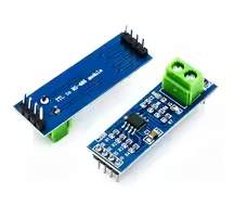
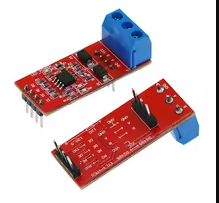
MAX485 Module RS-485 TTL to RS485 Converter
MAX485CSA Converter for Arduino and MCU Development
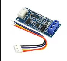
The MAX485 module is a TTL to RS485 converter that enables longdistance, reliable serial communication for Arduino and other microcontrollers. It converts standard UART signals to the RS485 differential standard, ideal for industrial and multinode networks.
Robust RS485 Communication - Supports distances up to 1200 meters
MultiNode Support Up to 32 devices on the same RS485 bus
Operating voltage is 3.3V to 5V - compatible with most MCUs
Tie RE and DE pins together for simple half-duplex control
Do not connect RS485 lines to both active devices with different ground potentials
Technical Specifications
| Parameter | Value |
|---|
| Chip | MAX485CSA |
| Supply Voltage | 3.3V to 5V |
| Data Rate | Up to 2.5Mbps |
| Communication | Half-duplex |
| Number of Nodes | 32 max |
| Transmission Distance | 1200 meters max |
| Receiver Enable | RE (active low) |
| Driver Enable | DE (active high) |
= Key Features =
LongRange Communication Up to 1200 meters using twisted-pair cable
MultiNode Support Connect up to 32 transceivers on the same bus
Low Power Operation - Shutdown current 0.5µA typical
ESD Protection - ±15kV ESD protection on RS485 pins
Screw Terminals - Easy connection for RS485 A/B lines
= Applications =
- Industrial automation and control
- Long-distance sensor networks
- Building management systems
- PLC communication
- Multi-drop data acquisition
- Distributed control systems
Standard RS485 Interface - Proven industrial communication protocol
Simple TTL Interface - Easy connection to Arduino and MCUs
√ Screw terminals for RS485 A/B connection
√ Onboard 120Ω termination resistor (jumper selectable)
√ LED indicators for power and data activity
Connection Guide
TTL side (to MCU):
- VCC: 3.3V to 5V power
- GND: Ground
- RO: Receiver output (to MCU RX)
- DI: Driver input (to MCU TX)
- RE: Receiver enable (active low)
- DE: Driver enable (active high)
RS485 side:
- A: Non-inverting line
- B: Inverting line
- GND: Ground (optional shield)
Connect RE and DE together for half-duplex control
Use a twisted pair cable for longer distances
Enable termination resistor only at the ends of the bus
Ensure all devices share a common ground potential
Wiring and Operation Examples
Simplest half-duplex wiring:
- Tie RE and DE to MCU control pin
- Set control pin HIGH to transmit
- Set control pin LOW to receive
For automatic direction control:
- Use a transistor inverter circuit
- Ideal for applications with fast switching
Easy Control - Simple digital pin for direction
Reliable Transmission - Differential signaling reduces noise
Compatible with Arduino, ESP32, and STM32
Widely used in industrial projects
Troubleshooting
No communication:
- Check VCC and GND connections
- Verify data rate matching
- Avoid reversed A/B connections
Data errors:
- Enable termination resistor
- Use twisted-pair cable
- Avoid ground loops