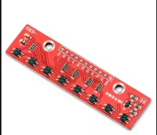
Line Follower Infrared Detection Sensor 8 Channel 8Bit Detector Hunt Board PCB Infrared Detection Sensor Module Board
KSH 500.00
In Stock
This 8channel infrared line follower sensor module features eight independent IR emitters and receivers arranged in a single board, providing highresolution line detection for robotic projects. It outputs digital 0/1 signals for each channel, making it ideal for Arduino and MCU-based line following applications .
| Parameter | Value |
|---|---|
| Number of Channels | 8 |
| Sensor Type | Infrared (IR) emitter/receiver pair |
| Output Format | Digital (0 or 1) |
| Operating Voltage | 3.8V to 5.5V |
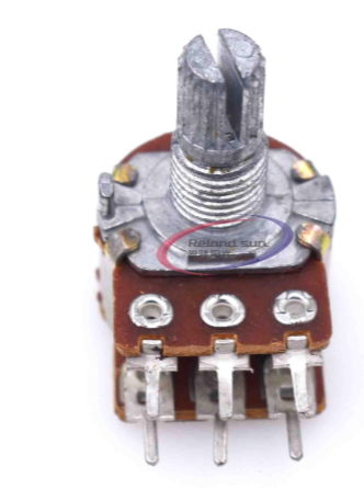
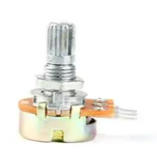
| Threshold Adjustment | Individual potentiometers per channel |
| Mounting Holes | M3 (for secure attachment to robot chassis) |
| PCB Color | Blue or Green |
= Key Features =
Independent Channel Outputs - Each channel provides a separate digital signal
Adjustable Threshold - Individual potentiometer per sensor allows tuning for different track colors and lighting conditions
High Sensitivity Detects black lines on white surfaces effectively, with a 315mm recommended distance
LED Indicators - Clear visual indication of channel status
Robust PCB Design - M3 mounting holes for easy installation on robot frames
Compatible with Popular MCUs - Works with Arduino, ESP32, STM32, and Raspberry Pi
√ Works with common Arduino code and libraries
√ Configurable for both white line on black track (and vice versa)
√ Easy integration with motor driver modules
The module typically includes 3 or 4 pins for power and ground, plus 8 individual output pins for each sensor channel. The I/O pins output a digital LOW when the sensor detects a black (or high-contrast) line, with the exact behavior depending on the mode setting (some modules offer light or dark mode via a jumper).
Sensor not detecting line:
Inconsistent readings:
All LEDs on/off: