XH-M131 5V Light Control Switch Photoresistor Relay Module
10A Brightness Automatic Control Module for Arduino
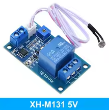
The XH-M131 is an automatic light control switch that uses a photoresistor to detect ambient brightness. When light falls below an adjustable threshold, its integrated relay activates, enabling 10A load switching for lighting and automation projects.
10A Relay Output - Controls AC 250V@10A or DC 30V@10A loads
Adjustable Sensitivity - Potentiometer sets exact light threshold
Arduino Compatible - Simple 5V logic interface
Input voltage is DC 5V with reverse polarity protection
Use NC/COM for alwayson, NO/COM for darkactivated control
Relay is not isolated from main power - use caution with AC loads
Technical Specifications
| Parameter | Value |
|---|
| Supply Voltage | 5V DC |
| Trigger Current | 20mA |
| Load Capacity | 10A 250VAC / 30VDC |
| Detection Frequency | 1MHz |
| LDR Probe Length | 30cm |
| Dimensions | 53x31x18mm |
= Key Features =
Optocoupler Isolation Protects control side from highvoltage loads
Adjustable Threshold Potentiometer finetunes activation point
Dual LED Indicators - RED (power), BLUE (relay active)
Three Relay Terminals - NO, COM, NC for flexible wiring
Reverse Polarity Protection - Prevents module damage
Four M3 Mounting Holes - Easy panel installation
= Applications =
- Automatic street and garden lighting
- Night lights and security lights
- Photocopy machines and medical equipment
- DIY automation and sensor projects
- Stage lighting and industrial control
Versatile Application - Works for both automation and Arduino projects
Ready to Use - LDR probe and screw terminals included
√ 30cm LDR probe for remote light sensing
√ Pre-soldered screw terminals for load wiring
√ Compact design fits standard enclosures
Connection Guide
Power connections:
- VCC: 5V DC positive
- GND: Ground
Relay output terminals:
- NO (Normally Open): Load connects here for dark activation
- COM (Common): Shared terminal
- NC (Normally Closed): Load connects here for light activation
Connect NO and COM for relay activation in darkness
For testing, adjust potentiometer with power applied
Keep high-voltage wiring separate from control wires
Operation Setup
Behavior adjustment:
- Turn potentiometer clockwise: Higher sensitivity (activates at brighter light)
- Turn potentiometer counterclockwise: Lower sensitivity (activates at darker conditions)
- Blue LED indicates relay is energized
The LDR probe can be extended up to several meters
Use heat shrink tube for outdoor probe protection
Relay contact rating is 10A maximum - use external contactor for heavier loads
Always fuse the load circuit appropriately
Troubleshooting
Relay not activating:
- Adjust potentiometer while covering LDR
- Verify 5V power supply is stable
- Avoid direct sunlight on LDR
Inconsistent operation:
- Check LDR probe placement
- Clean LDR sensor surface
- Avoid EMI from adjacent equipment