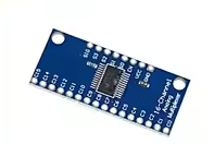
74HC4067 16-Channel Analog Digital Multiplexer Breakout Board
CD74HC4067 Module for Arduino DIY Projects
This 74HC4067 multiplexer board expands 16 analog or digital input channels using just 4 control pins. Ideal for Arduino projects requiring multiple sensor inputs with minimal GPIO usage.
16to1 Multiplexing - Reads 16 inputs with only 4 control pins
Low OnResistance 60Ω typical for reliable analog readings
Connect common pin to Arduino analog input
Use digital pins for selection lines
Do not exceed 6V supply voltage
Technical Specifications
| Parameter | Value |
|---|
| IC Type | 74HC4067 / CD74HC4067 |
| Channels | 16 inputs/outputs |
| Supply Voltage | 2V to 6V |
| Control Pins | 4 (S0-S3) |
| Enable Pin | Active low (EN) |
| On-Resistance | 60Ω typical |
| Bandwidth | 50MHz |
= Key Features =
Expands I/O Capacity - 16 channels from 4 control pins
Bidirectional - Works for analog or digital signals
Breakout Board Design - Easy connection points
Low Power Consumption - Minimal current draw
Wide Voltage Range - 2V to 6V operation
= Applications =
- Multi-sensor monitoring
- Analog signal multiplexing
- LED matrix control
- Audio signal routing
- Data acquisition systems
- Test equipment expansion
GPIO Saver - Saves microcontroller pins
Reliable Switching - Low resistance for accuracy
√ Labeled pin headers
√ 16 individual channel pins
√ Common pin for connection
Connection Guide
Control pins:
- S0, S1, S2, S3: Channel select
- EN: Enable (low to activate)
- COMMON: Shared input/output
- VCC: 2-6V power
- GND: Ground
Channel selection:
- Binary input on S0-S3 selects channel
- 0000 Channel 0, 1111 Channel 15
- Enable low to activate
Connect COMMON to Arduino analog pin
Use binary math for channel selection
Enable pin must be low to operate
Connect VCC before applying signals
Arduino Usage Example
Select channel 5:
- S0 high (1), S1 low (0), S2 high (1), S3 low (0)
- Binary 0101 = Channel 5
- Enable low to activate connection
For analog input:
- Connect COMMON to Arduino analog pin
- Read selected channel using analogRead()
- Switch channels to scan multiple sensors
Simple Control - DigitalWrite for selection
Quick Scanning - Read all 16 channels rapidly
Compatible with analog and digital signals
Works with 5V and 3.3V logic
√ Channel pins labeled for easy identification
√ Enables multiple sensor projects
√ Great for beginners and experts
Channel Selection Table
Binary S3S2S1-S0 selects channel:
- 0000 Ch0, 0001 Ch1
- 0010 Ch2, 0011 Ch3
- 0100 Ch4, 0101 Ch5
- 0110 Ch6, 0111 Ch7
- 1000 Ch8, 1001 Ch9
- 1010 Ch10, 1011 Ch11
- 1100 Ch12, 1101 Ch13
- 1110 Ch14, 1111 Ch15
Set EN pin LOW before selecting channels
Use shift registers for more expandability
Do not leave EN pin floating
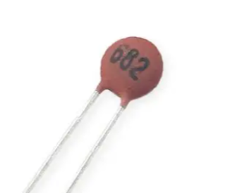
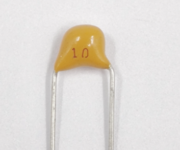
Use capacitor for noise filtering
Troubleshooting
Wrong channel selected:
- Check binary pin states
- Verify S0-S3 connections
- Avoid floating control pins
Inconsistent readings:
- Add capacitor on analog input
- Use averaging for noisy signals
- Avoid long unshielded wires