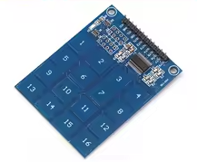
TTP229 16-Channel Capacitive Touch Sensor Module
Digital Touch Button Keypad for Arduino Projects
The TTP229 module provides 16 capacitive touch keys through a 4x4 matrix pad, functioning as a durable, modern alternative to traditional mechanical buttons for Arduino and MCU projects [citation:1].
16 Capacitive Touch Channels - 4x4 grid with touch or proximity detection [citation:1]
Low Power Consumption - Only 2.5µA standby current (at 3V) for battery projects [citation:4][citation:8]
Operating voltage is 2.4V to 5.5V - compatible with 3.3V and 5V logic systems [citation:1][citation:4]
The module communicates via a 2wire serial protocol (SCL/SDO) but it is not standard I2C—treat it as a custom clockand-data scheme [citation:2][citation:5]
Short the TP2 jumper to enable 16-key mode (factory default may set to 8 keys) [citation:2][citation:5]
Technical Specifications
| Parameter | Value |
|---|
| Touch Channels | 16 (4x4 matrix) |
| Interface | 2-wire serial (SCL/SDO) |
| Supply Voltage | 2.4V to 5.5V |
| Standby Current | 2.5µA (16-key mode) |
| Response Time | 50ms to 100ms |
| Operating Temperature | -40°C to +85°C |
| Dimensions | 49.3mm x 64.5mm (varies) |
= Key Features =
Capacitive Touch Technology Detects touch through nonconductive materials
Only 2 Pins Required - Uses just SCL and SDO for all 16 keys
Auto Calibration - Adjusts to environmental changes automatically
Adjustable Sensitivity - Tune via external capacitors
Interrupt Support - INT pin triggers events on touch
= Applications =
- Custom control panels and HMI interfaces
- Replacement for worn-out membrane keypads
- Waterproof or sealed user interfaces
- Educational MaKey MaKey-style projects
- Battery-powered remote controls
Durable and Modern - No mechanical wear or moving parts
Simple Interface 2wire communication saves GPIO pins
√ Onboard power indicator LED
√ TP2 jumper for 16-key mode selection
√ Ready for Arduino, ESP32, Raspberry Pi
Connection Guide
Module pins:
- VCC: 2.4V to 5.5V power
- GND: Ground
- SCL: Clock input (Arduino digital pin)
- SDO: Data output (Arduino digital pin)
- INT: Interrupt output (optional)
Wiring to Arduino:
- VCC: 3.3V or 5V
- GND: Ground
- SCL: Digital pin (e.g., D10)
- SDO: Digital pin (e.g., D11)
Use 4.7kΩ pull-up resistors on SCL and SDO for signal stability [citation:6]
Short TP2 jumper with a solder bridge or jumper cap to enable all 16 keys [citation:2][citation:5]
Do not use standard I2C libraries this module uses a pulsebased serial protocol [citation:5][citation:10]
Programming Instructions
Install a TTP229 library via Arduino IDE or use code similar to the example below [citation:3][citation:10][citation:11]:
Basic reading logic:
- Pulse SCL pin 16 times
- Read SDO state after each pulse
- Key pressed = pulse number when SDO is LOW (active-low mode)
- Return detected key number
Code structure:
- Define SCL and SDO pins
- In setup: set SCL as OUTPUT, SDO as INPUT
- In loop: pulse SCL 16 times, read SDO, output key if pressed
Key mapping:
- Key 1 = first pulse (bit 0)
- Key 16 = last pulse (bit 15)
Simple Logic - Pulse clock and read data
NonBlocking Can be read in loop with delay
Works with Arduino, ESP8266, and STM32
Reliable touch detection in most conditions
Troubleshooting
No keys detected:
- Verify TP2 jumper is shorted (for 16-key mode)
- Check VCC, GND, and signal connections
- Avoid using standard I2C library
Inconsistent readings:
- Add 4.7kΩ pull-up resistors on SCL and SDO
- Shorten wire length between module and MCU
- Avoid placing module near metal surfaces
- Touch pads require direct finger contact