ESP32 C3 Super mini V2.0 Red Board – KSH 1,300 at HIMASTORES Mombasa – best electronics in Kenya

ESP32 C3 Super mini V2.0 Red Board

SKU: HMJ565 Category: Microcontrollers
KSH 1,300.00
In Stock

Product Description

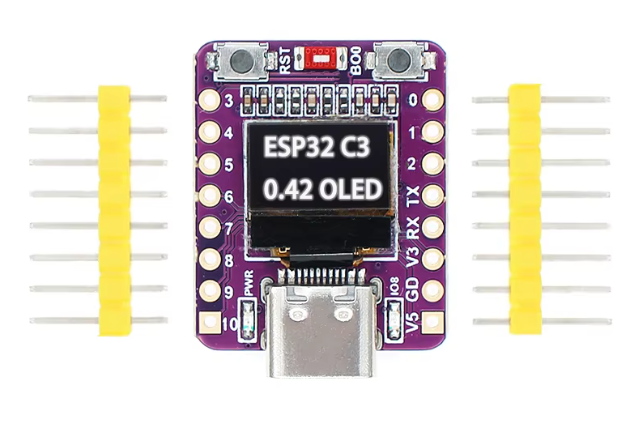
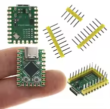
ESP32-C3 SuperMini V2.0 Red Board

UltraCompact RISCV Development Board with USB-C

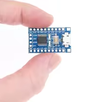
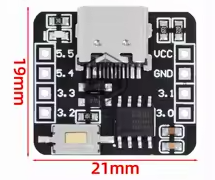
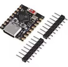
The ESP32C3 SuperMini V2.0 Red Board is a highly compact development board based on the ESP32C3 RISCV singlecore processor, running at up to 160 MHz [citation:2][citation:5][citation:8]. It provides WiFi 4 and Bluetooth 5.0 (LE) in a tiny 22.52 x 18mm form factor, making it perfect for spaceconstrained IoT and wearable projects [citation:1][citation:8].

RISCV SingleCore Processor 32bit core running at 160 MHz with FPU support
4MB Flash & 400KB SRAM - Ample storage and memory for complex projects
Operating voltage is 3.3V with 5V power via USBC or 3.3V6V via pins [citation:5][citation:11]
Use GPIO8 for the onboard blue LED (inverted logic: LOW = ON) and the RGB NeoPixel (WS2812B) [citation:1][citation:11]
Avoid using GPIO8 for I2C (SDA) as it conflicts with both onboard LEDs and may cause unpredictable behavior [citation:1]

Technical Specifications

ParameterValue
ProcessorESP32C3 RISCV single-core [citation:2]
Clock Speed160 MHz [citation:2][citation:5]
Flash Memory4MB [citation:3][citation:5]
SRAM400KB [citation:5][citation:8]
Wi-Fi802.11 b/g/n (2.4GHz) [citation:5]
Bluetooth5.0 LE [citation:2][citation:5]
ADC Channels6 x 12-bit [citation:3][citation:6]
GPIO Pins13 usable (10 freely configurable) [citation:11]
USBUSB-C (CDC, DFU, HID) [citation:5]
Power ConsumptionDeep sleep ~43µA [citation:2][citation:8]
Dimensions22.52 x 18mm [citation:2][citation:8]

= Key Features =

UltraCompact Fits into tight enclosures and wearables

USBC Native Programming No external adapter needed, supports CDC for serial output [citation:5][citation:7]

Onboard Dual LEDs - Blue LED (GPIO8) and RGB NeoPixel (WS2812B) [citation:1]

Low Power Consumption - 43µA deep sleep ideal for battery projects [citation:2][citation:8]

External Antenna Support IPEX connector for enhanced WiFi/BT range [citation:5]

Strapping Pin Management - GPIO8, GPIO9, and GPIO2 control boot modes [citation:11]

= Applications =

  1. Low-power IoT sensors and smart home devices
  2. Wearable electronics and portable gadgets
  3. Wireless keyboard, mouse, and HID projects
  4. Bluetooth LE peripherals and beacons
  5. Space-constrained Arduino and MicroPython projects
Highly CostEffective Affordable board with powerful RISC-V core
Flexible Pin Mapping - GPIO matrix allows routing interfaces to various pins

√ Compatible with Arduino IDE, ESP-IDF, and MicroPython [citation:5][citation:10]

√ Onboard buttons for RESET and BOOT (GPIO9) for easy firmware upload [citation:10]

√ Breadboard-friendly with 2.54mm pin pitch [citation:5]

Special Pin Considerations

The board uses a shared GPIO8 for both the blue status LED and the RGB NeoPixel [citation:1][citation:11]. This shared configuration requires careful handling to avoid conflicts between PWM control for the blue LED and the timing-critical NeoPixel data stream [citation:1].

*Critical GPIO Notes:*

  • *GPIO8*: Shared between blue LED (inverted) and RGB NeoPixel. Avoid using for other peripherals [citation:1][citation:11]
  • *GPIO9*: Connected to BOOT button, pulled HIGH during boot [citation:11]
  • *GPIO2*: Strapping pin for boot mode selection [citation:11]
  • *GPIO4-7*: Reserved for JTAG debugging [citation:3][citation:9]
Use dedicated libraries to manage the shared GPIO8 LED conflict [citation:1]
For stable I2C, use GPIO1 (SDA) and GPIO3 (SCL) instead of default pins [citation:11]
Connect 5V pin or 3.3V-6V via VBUS for external power [citation:5][citation:11]

Firmware Upload Procedure

  1. Hold down the *BOOT* button (GPIO9)
  2. Press and release the *RESET* button
  3. Release the *BOOT* button
  4. Board enters download mode for programming [citation:10]
For Arduino IDE, select *ESP32C3 Dev Module board and enable USB CDC On Boot* for serial output [citation:1][citation:10]

Troubleshooting

Board not detected:

  • Use a datacapable USBC cable
  • Install CH343 or CP210x USB drivers if needed

No serial output:

  • Enable USB CDC On Boot in Arduino IDE settings [citation:10]
  • Check for correct port selection

Firmware upload fails:
  • Follow the BOOT+RESET sequence correctly [citation:10]
  • Avoid using GPIO8, GPIO9 during boot as strapping pins